2006-2016 Volkswagen Crafter
Fitting locations overview
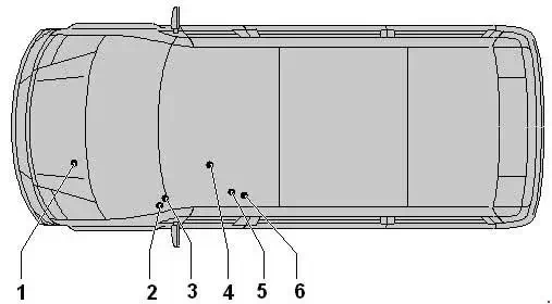
- Terminal 30 voltage supply fuse -S190-
- Fuse block (SA) on the battery
- Fuse box (SB) on left A-pillar
- Fuse box (SC) on left A-pillar
- Fuse box (SD) under driver seat
- Single fuses under driver seat
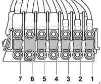
Fuse holder (SA), on the battery
| No. | A | Description |
|---|---|---|
| 1 | 80 | Automatic glow period control unit |
| 2 | 40 | with air conditioning system: Radiator fan control unit Radiator fan Right radiator fan |
| 3 | 80 | Onboard supply control unit Engine component current supply relay Fuse holder C -SC- SC2, SC3, SC8 - SC10, SC16 |
| 4 | 150 | Auxiliary battery Tipping mechanism fuse (→August 2006) Fuse 1 (30) (July 2006→) Fuse 2 (30) (September 2006→) Main fuse for multiple equipment configurations (→August 2006) Fuse holder D -SD- SD23 - SD25, SD28 (September 2006→ (with second battery)) |
| 5 | 150 | Terminal 15 voltage supply relay Horn relay Onboard supply control unit Terminal 15 voltage supply relay 2 Start/Stop operation fuse (November 2011→) Fuse holder B -SB- SB1 - SB18 Fuse holder C -SC- SC4 - SC7, SC11 - SC15, SC17 - SC25 |
| 6 | - | Terminal 15 relief relay Voltage supply relay 1 (November 2013→) Relief relay 2 for terminal 15 (only for models in the 3.8 t weight class) Relief relay 3 for terminal 15 (November 2011→) Fuse for heated front windscreen Fuse 1 (November 2011→) Fuse 1 (30) (→June 2006) Fuse holder D -SD- SD10 - SD33, SD42 |
| 7 | 150 | Auxiliary air heater element |
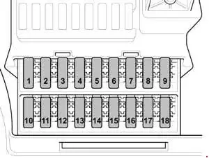
Fuse Block (SB), Left A-pillar
| No. | A | Description |
|---|---|---|
| 1 | 25 | Driver door control unit |
| 2 | 10 | Diagnostic connection |
| 3 | 25 | ABS control unit |
| 4 | 40 | ABS control unit |
| 5 | - | - |
| 6 | 7.5 | November 2008-May 2009: Evaluation unit for reducing agent level Reverse flow valve for reducing agent Pump for reducing agents |
| 7.5 | November 2013→: Supply unit for reducing agent metering system NOx sensor control unit Relay 1 for voltage supply NOx sensor 2 control unit Relay for reducing agent metering system Pump for reducing agent |
|
| 7 | 30 | Headlight washer system pump |
| 8 | 15 | Rotating light and siren system switch (July 2006→) Switch for rotating light (July 2006→) Alarm horn Alarm system relay 1 Siren system relay 2 (July 2006→) |
| 9 | 10 | May 2007→: Turn signal relay for roof mounted turn signals |
| 10 | 15 | Radio Control unit with display for radio and navigation |
| 11 | 7.5 | Mobile telephone operating electronics control unit Tachograph control unit |
| 12 | 30 | Heater/heat output switch Fresh air blower relay Fresh air blower control unit Fresh air blower |
| 13 | 7.5 | Pre-selection clock Remote control receiver for auxiliary coolant heater |
| 14 | 30 | Operating unit for centre dash panel |
| 15 | 10 | →October 2008: Load area illumination switch |
| 16 | 10 | Heater/heat output switch A/C control module CD changer |
| 17 | 10 | Interior illumination switch Rear interior lamp switch (November 2012-May 2013) |
| 18 | - | - |
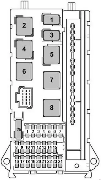
Fuse Block (SC), Left A-pillar
| No. | A | Description |
|---|---|---|
| 1 | 15 | Treble horn |
| 2 | 25 | Electronic ignition lock El. steer. col. lock CU |
| 3 | 10 | Electronic ignition lock Control unit in dash panel insert Engine control unit (May 2012→) |
| 4 | 5 | Light switch Operating unit for centre dash panel |
| 5 | 30 | Windscreen wiper motor |
| 6 | 15 | Fuel system pressurisation pump |
| 7 | 5 | Steering column electronics control unit |
| 8 | 20 | Engine control unit |
| 9 | 20 | November 2008-May 2009: Fuse 6 on fuse holder B -SB6- |
| 25 | May 2009-November 2013: Fuse holder D -SD- SD34 - 36 | |
| 10 | 10 | Fuel pressure regulating valve |
| 10 | May 2012→: Air mass meter Evaluation unit for reducing agent level Heater element for crankcase breather Fuel pressure regulating valve Exhaust gas recirculation cooler changeover valve Reverse flow valve for reducing agent Exhaust gas recirculation cooler pump Pump for reducing agent |
|
| 11 | 15 | Relief relay 2 for terminal 15 (only for models in the 3.8 t weight class) Fuse 1 on fuse holder D Fuse 2 on fuse holder D |
| 12 | 10 | Airbag control unit |
| 13 | 15 | Glove compartment light switch Cigarette lighter |
| 14 | 5 | Light switch Control unit in dash panel insert Diagnostic connection |
| 15 | 5 | Heater/heat output switch Headlight range control regulator Left headlight range control motor Right headlight range control motor |
| 16 | 10 | Main switch for stop/start system Gearbox neutral position switch Oil level and oil temperature sender Fuel pump relay Continued coolant circulation relay Automatic glow period control unit Terminal 50 voltage supply relay Starter relay 1 (November 2013→) Starter relay 2 (November 2013→) Charge pressure control solenoid valve Coolant circuit valve Exhaust flap valve (November 2013→) Fuel metering valve Exhaust gas recirculation cooler changeover valve Lambda probe heater |
| 17 | 10 | Airbag control unit |
| 18 | 7.5 | July 2006-November 2011: Brake light switch Brake pedal switch Relief relay for terminal 15 |
| 7.5 | November 2011→: Relief relay for terminal 15 Voltage stabiliser Relay for special constructions, terminal 15 Relief relay 3 for terminal 15 |
|
| 19 | 7.5 | Onboard supply control unit (Interior light) |
| 20 | 25 | Onboard supply control unit |
| 21 | 5 | Air mass meter Engine control unit |
| 22 | 5 | →June 2006: Brake light switch Brake pedal switch |
| 5 | July 2006→: Lateral acceleration sensor Longitudinal acceleration sensor ABS control unit |
|
| 23 | 25 | Starter Onboard supply control unit |
| 24 | 10 | -Reserve Kl. 15- Battery regulation control unit (May 2013→) |
| 25 | 30 | 12-V socket |
Fuse Block (SD), Under Driver Seat (→May 2011)
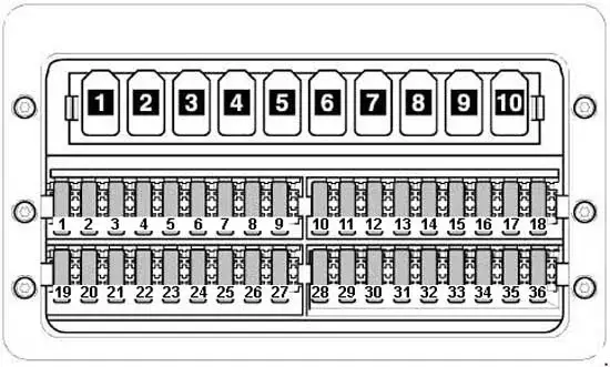
| No. | A | Description |
|---|---|---|
| 1 | 5 | Operating unit for window regulator in driver door Heated rear window relay (→June 2006) Relay 2 for heated rear window (July 2006→) |
| 2 | 30 | Rear left wing door window wiper motor Rear window wiper motor in right wing door |
| 3 | 5 | Pre-selection clock Gearbox neutral position switch Display unit control unit Mobile telephone operating electronics control unit (→May 2011) Reversing camera |
| 4 | 7.5 | Working speed control switch (July 2006→) Power take-off warning switch (July 2006→) Relay for heated rear window (→June 2006) Trailer detector control unit Tachograph control unit (July 2006→) |
| 5 | 5 | Selector lever Automated manual gearbox control unit |
| 10 | Selector lever Automated manual gearbox control unit |
|
| 6 | 5 | Battery regulation control unit (→May 2013) Heater element for crankcase breather |
| 7 | 10 | Fuel filter heater |
| 8 | 5 | Tilting mechanism button Relay for special constructions, terminal 15 6-pin connector (May 2007→) 7-pin connector (Tail lift coupling point) |
| 10 | Tilting mechanism button Relay for special constructions, terminal 15 6-pin connector (May 2007→) 7-pin connector (Tail lift coupling point) |
|
| 9 | 15 | Switch for roof ventilator to ventilate loading area Siren system relay |
| 10 | 25 | -Interface for external use- |
| 11 | 15 | Relay for special constructions, terminal 15 |
| 12 | 10 | Relay for special constructions, terminal 61 |
| 13 | 30 | May 2007-May 2011: Evaporator blower control unit |
| 10 | →May 2007: Turn signal relay for roof mounted turn signals | |
| 14 | 20 | →August 2006: Trailer detector control unit |
| 20 | September 2006→: 9-pin connector (Preliminary set-up for trailer attachment) Trailer socket |
|
| 15 | 25 | Trailer detector control unit |
| 16 | 7.5 | Parking aid control unit Tyre Pressure Monitoring System control unit |
| 17 | 25 | Control unit for programmable special functions |
| 18 | 25 | Control unit for programmable special functions |
| 19 | 5 | Roof electronics control unit |
| 25 | Roof electronics control unit | |
| 20 | 7.5 | →May 2009: Continued coolant circulation relay |
| 10 | May 2009→: Continued coolant circulation relay Entry and footwell light relay |
|
| 21 | 15 | Heated rear window relay |
| 30 | Heated rear window relay | |
| 22 | 15 | Heated rear window relay (→June 2006) Relay 2 for heated rear window |
| 23 | 10 | Load area illumination switch (November 2008→) 12 V socket 2 |
| 15 | Load area illumination switch (November 2008→) 12 V socket 2 |
|
| 24 | 15 | 12 V socket 4 |
| 25 | 15 | 12 V socket 3 |
| 26 | 25 | Auxiliary heater control module |
| 27 | 20 | Auxiliary heater control module Control unit 2 for supplementary heating |
| 25 | Auxiliary heater control module Control unit 2 for supplementary heating |
|
| 28 | 30 | →April 2007: Evaporator blower control unit |
| 40 | May 2007→: Gearbox hydraulic pump relay | |
| 29 | 15 | Automated manual gearbox control unit |
| 30 | 40 | Gearbox hydraulic pump relay (→April 2007) Battery regulation control unit - |
| 31 | 30 | Rear fresh air blower control unit Left sliding door control unit Rear fresh air blower |
| 15 | Rear fresh air blower control unit Left sliding door control unit Rear fresh air blower |
|
| 32 | 5 | Battery monitoring control unit |
| 33 | 15 | Right sliding door control unit |
| 34 | 15 | April 2009→: Control unit for reducing-agent heater |
| 35 | 15 | April 2009→: Control unit for reducing-agent heater |
| 3 | April 2009→: Control unit for reducing-agent heater | |
| 36 | - | - |
Fuse Block (SD), Under Driver Seat (May 2011→)
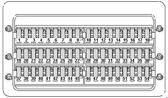
| No. | A | Description |
|---|---|---|
| 1 | 5 | Operating unit for window regulator in driver door Heated rear window relay 2 |
| 2 | 30 | Rear left wing door window wiper motor Rear window wiper motor in right wing door |
| 3 | 5 | Pre-selection clock Gearbox neutral position switch Display unit Reversing camera |
| 4 | 7.5 | Working speed control switch Power take-off warning switch Trailer detector control unit Tachograph control unit |
| 5 | 5 | →November 2011: Selector lever Automated manual gearbox control unit |
| 10 | November 2011→: Selector lever Automated manual gearbox control unit Bonnet contact switch |
|
| 6 | 5 | Heater element for crankcase breather Battery regulation control unit (from May 2011 to May 2013) |
| 10 | Heater element for crankcase breather Battery regulation control unit (from May 2011 to May 2013) |
|
| 7 | 10 | Fuel filter heater |
| 8 | 5 | Tilting mechanism button Parking aid control unit (May 2013→) Relay for special constructions, terminal 15 (→November 2011) 6-pin connector 7-pin connector (Tail lift coupling point) |
| 10 | Tilting mechanism button Parking aid control unit (May 2013→) Relay for special constructions, terminal 15 (→November 2011) 6-pin connector 7-pin connector (Tail lift coupling point) |
|
| 9 | 15 | →November 2011: Switch for roof ventilator to ventilate loading area Siren system relay |
| 10 | 25 | Interface for external use |
| 11 | 15 | Relay for special constructions, terminal 15 |
| 12 | 10 | Relay for special constructions, terminal 61 |
| 13 | - | - |
| 14 | 20 | 9-pin connector (Preliminary set-up for trailer attachment) Trailer socket |
| 15 | 25 | Trailer detector control unit |
| 16 | 7.5 | Parking aid control unit Tyre Pressure Monitoring System control unit |
| 17 | 25 | Control unit for programmable special functions |
| 18 | 25 | Control unit for programmable special functions -J8 |
| 19 | 5 | Roof electronics control unit |
| 25 | Roof electronics control unit | |
| 20 | 7.5 | Continued coolant circulation relay Entry and footwell light relay |
| 10 | Continued coolant circulation relay Entry and footwell light relay |
|
| 21 | 30 | Heated rear window relay |
| 22 | 15 | Heated rear window relay 2 |
| 23 | 10 | Load area illumination switch 12 V socket 2 |
| 15 | Load area illumination switch 12 V socket 2 |
|
| 24 | 15 | 12 V socket 4 |
| 25 | 15 | 12 V socket 3 |
| 26 | 25 | Auxiliary heater control module |
| 27 | 20 | Auxiliary heater control module Control unit 2 for supplementary heating |
| 25 | Auxiliary heater control module Control unit 2 for supplementary heating |
|
| 28 | 40 | Gearbox hydraulic pump relay Starter relay 1 |
| 30 | Gearbox hydraulic pump relay Starter relay 1 |
|
| 29 | 15 | Automated manual gearbox control unit |
| 30 | 5 | Battery regulation control unit |
| 31 | 30 | May 2012→: Left sliding door control unit ( |
| 15 | Rear fresh air blower control unit Rear fresh air blower |
|
| 32 | 5 | Battery monitoring control unit |
| 33 | 30 | May 2012→: Right sliding door control unit |
| 7.5 | January 2012→: Lockout relay 1 for transfer box Lockout relay 2 for transfer box Lockout relay 3 for transfer box Compressed air compressor |
|
| 34 | 15 | January 2012→: Control unit for reducing-agent heater |
| 7.5 | January 2012→: Transfer box differential lock switch Rear axle drive unit differential lock switch Front axle drive unit differential lock switch |
|
| 35 | 15 | Control unit for reducing-agent heater |
| 3 | January 2012→: Compressed air compressor protection control unit | |
| 36 | 5 | January 2012→: Compressed air compressor pressure switch |
| 37 | - | - |
| 38 | - | - |
| 39 | 7.5 | →November 2011: Switch for roof ventilator to ventilate loading area |
| 15 | November 2011→: Siren system relay | |
| 40 | - | - |
| 41 | - | - |
| 42 | 30 | Evaporator blower control unit |
| 43 | - | - |
| 44 | - | - |
| 45 | - | - |
| 46 | - | - |
| 47 | - | - |
| 48 | - | - |
| 49 | - | - |
| 50 | - | - |
| 51 | - | - |
| 52 | - | - |
| 53 | - | - |
| 54 | - | - |
| 55 | - | - |
| 56 | - | - |
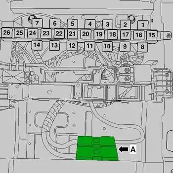
Single fuses under driver seat (for special vehicles →May 2013)
A - Tipping mechanism fuse -S186- Up to August 2006
A - Fuse 1 (30) (Retarder/Second battery)
A - Fuse 2 (30) after September 2006 (Tail lift/three-way tipper/Retarder)
A - Main fuse for multiple equipment configurations -S245- Up to August 2006
Single fuses under driver seat (for special vehicles May 2013→)
A - Fuse 1 (30) (Retarder/Second battery)
A - Fuse 2 (30) (Tail lift/three-way tipper/Retarder)
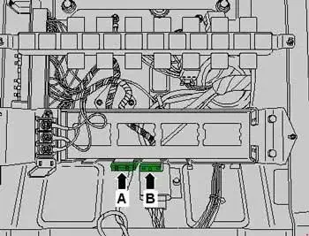
A - Daytime running lights fuse (Achleitner only)
B - Fuse 1 (Compressed air compressor)
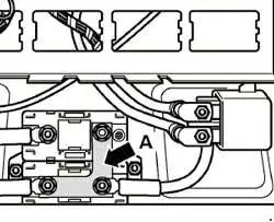
Terminal 30 voltage supply fuse -S190- (1)
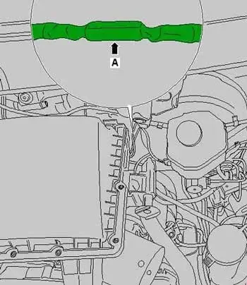
A - Terminal 30 voltage supply fuse (in the line section between the alternator and the starter)