Bobcat 325 & 328

Location and description of fuses and relay Mini Excavator Bobcat 325 and Bobcat 328
Fuse Box
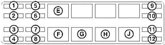
| No. | A | Description |
|---|---|---|
| 1 | - | Not Used |
| 2 | 25 | Heater |
| 3 | 5 | Ignition |
| 4 | 25 | Fuel Solenoid |
| 5 | 5 | Wiper |
| 6 | 20 | Switch Power |
| 7 | 25 | Alternator/Heater |
| 8 | 25 | ACD (Attach. Control Device) |
| 9 | 25 | Controller |
| 10 | 25 | ACD (Attach. Control Device) |
| 11 | 20 | Lights |
| 12 | 15 | Accessory Plug |
| Relay | ||
| E | Switched Power | |
| F | Fuel Solenoid | |
| G | Lights | |
| H | Glow Plugs | |
| J | Starter | |
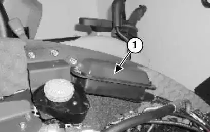
The Excavator has a 12 volt, negative ground electrical system. The electrical system is protected by fuses located under the right side cover of the Excavator (Item 1). The fuses will protect the electrical system when there is an electrical overload. The reason for the overload must be found before starting the engine again.