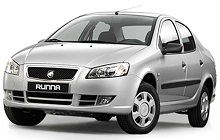
Iran Khodro Runna Fuse Box Diagram
Engine Compartment Fuse box
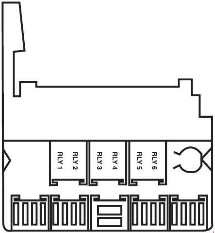
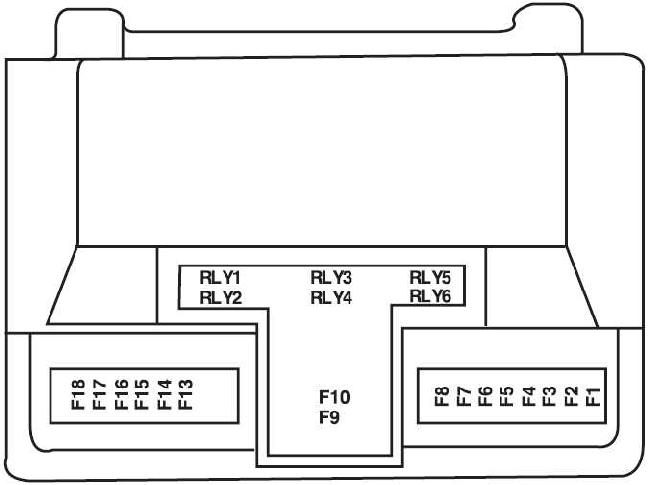
Fuse box is in the right part of the engine compartment. To access the fuse located in the engine compartment, unclip the fuse box cover. Close the fuse box cover carefully when you have finished.
| No. | A | Function |
| 1 | 40 | Power supply for ignition switch - Immobilizer |
| 2 | 20 | SPS*: Power supply of front node internal systems |
| 30 | Relay switch for fog lamp - horn | |
| 3 | 20 | SPS*: Connector power supply of front node internal systems |
| 40 | Connector power supply of BCM internal systems | |
| 4 | 20 | SPS*: Connector power supply of front node internal systems |
| 30 | Connector power supply of BCM internal systems | |
| 5 | 10 | SPS*: Relay switch for small lights |
| 6 | - | Spare |
| 7 | 40 | SPS*: Brake (ABS) |
| 30 | Brake (ABS) | |
| 8 | 30 | Brake (ABS) |
| 9 | 40 | SPS*: Fan (High and Low speed) Connector power supply of BCM internal system |
| 10 | 70 | SPS*: Connector power supply of BCM internal systems |
| 50 | Connector power supply of BCM internal systems | |
| 11 | 20 | SPS*: Relay switch for horn |
| 40 | Connector power supply of BCM internal systems | |
| 12 | 30 | SPS*: Starter supply |
| 20 | Front node supply | |
| 13 | 15 | Front node supply |
| 14 | 30 | Relay switch for front windshield wiper |
| 15 | 10 | SPS*: Sensor oxygen power |
| 16 | 40 | SPS*: Double relay supply |
| 30 | Double relay supply | |
| 17 | 10 | Fuel pump supply and Engine unit |
| 18 | 10 | Engine unit supply |
| Relay | ||
| R1 | Relay switch for engine control | |
| R2 | Relay switch for fuel pump | |
| R3 | Relay switch for small light Relay switch for fog lamp |
|
| R4 | Relay switch for horn | |
| R5 | Relay switch for front windshield wiper | |
| R6 | Relay switch for front windshield wiper | |
*Sazeh Pooyesh System
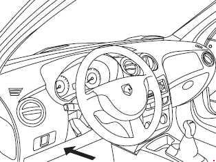
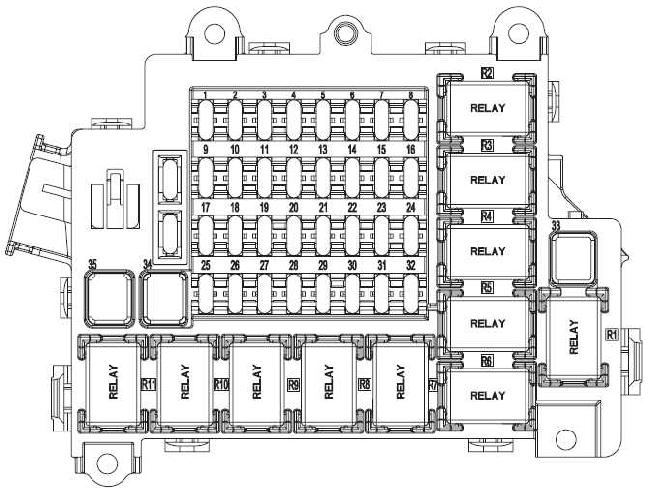
Fuse Box Under Dashboard (T1)
| No. | A | Function |
| F1 | - | Reserve |
| F2 | 5 | Heating fan relay |
| F3 | 5 | Power supply of front node FCM, cooler, Instrument panel |
| F4 | 10 | Power supply of rear wiper motor and trunk lock |
| F5 | 5 | Power supply of background light |
| F6 | 5 | Power supply of anti-lock braking system ABS |
| F7 | 10 | Power supply of airbag unit |
| F8 | 5 | Power supply of Instrument panel, immobilizer, DIAG, ECU |
| F9 | 5 | Power supply of wiper washer pumps |
| F10 | 5 | Power supply of central node of BCM, Front windows requlator display, reverse pear sensor. |
| F11 | 10 | Power supply of reverse gear |
| F12 | 5 | Power supply of Brake Light Switch |
| F13 | 10 | A three-position switch power supply of Cooler |
| F14 | 5 | Power supply of ceiling lights, trunk |
| F15 | 20 | Power supply of Lighter |
| F16 | 10 | Power supply of Radio Player |
| F17 | - | Reserve |
| F18 | - | Reserve |
| F19 | - | Reserve |
| F20 | - | Reserve |
| F21 | - | Reserve |
| F22 | 10 | Power supply of Front Window Regulators |
| F23 | 5 | Power supply of mirrors heater. |
| F24 | 30 | Power supply of rear glass heater |
| F25 | 30 | Power supply of central lock. |
| F26 | 20 | Power supply of central node BCM |
| F27 | 5 | Power supply of relays, monitors Cooler |
| F28 | 20 | Power supply of central node BCM |
| F29 | 5 | Power supply of Immobilizer |
| F30 | 10 | Power supply of radio memory |
| F31 | - | Reserve |
| F32 | - | Reserve |
| F33 | 40 | Power supply of Heater Fan |
| F34 | 40 | Power supply of front windows regulator, mirror |
| F35 | 40 | Power supply of rear window Regulators |
| F36 | 5 | Reserve |
| F37 | 10 | Reserve |
| Relay | ||
| R1 | Fan Relay | |
| R2 | Instrument panel relay, cooler and front node FCM | |
| R3 | Voltage relay ECO | |
| R4 | Rear of rear glass heater and side mirrors | |
| R5 | Front wiper washer pump relay | |
| R6 | - | |
| R7 | - | |
| R8 | Rear window regulator Relay | |
| R9 | Trunk opener and rear wiper relay | |
| R10 | Central opener relay | |
| R11 | Central door locking relay | |
Fuse Box Under Dashboard (T2)
| No. | A | Function |
| F21 | - | Spare |
| F22 | 10 | Main switch supply (position 2) air bag unit and central node |
| F23 | 20 | Main switch supply (position 1) lighter |
| F24 | 10 | Main switch supply - position 1 (motivation of heater relay * Radio, brake light, front node, central node and instrument panel) |
| F25 | 10 | Radio permanent supply |
| F26 | 20 | Central node supply |
| F27 | 20 | Central node supply |
| F28 | 30 | Central node supply and main supply and motivation of rear door motive relay |
| F29 | 30 | Rear window control supply |
| F30 | 30 | Central node supply (Front lifting window) |
| F31 | 30 | Rear window heater |
| F32 | 30 | Heater fan supply |
| F33 | 30 | Engine ignition |
| F34 | 10 | Main switch supply (position 2) immobilizer, diagnostic connector, instrument panel, cooler gas pressure sensor, engine unit. |
| F35 | 5 | Main switch supply (position 2), Anti-brake system (ABS). |
| F36 | 10 | Immobilizer permanent supply, diagnostic connector, instrument panel, motivation of window heater * windscreen washer pump, Multipurpose Instrument Panel |
| Relay | ||
| R1 | Front windscreen washer Pump | |
| R2 | Trunk lid unlocking | |
| R3 | Mirrors and rear window heater | |
| R4 | Heater Fan | |
| R5 | Rear Window Control | |
| R6 | - | |
| R7 | - | |
| R8 | - | |

