IKCO Samand Soren Fuse Box Diagram
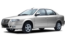
Fuse Box Layout IKCO Samand Soren (2007, 2008, 2009, 2010, 2011, 2012, 2013, 2014, 2015, 2016, 2017, 2018)
Fuse box on the dashboard


| No. | A | Function |
| F1 | 20 | Front seat electricity |
| F2 | 10 | Ignition switch 1, 2 Radio electricity |
| F3 | 20 | Lighter electricity |
| F4 | - | - |
| F5 | 30 | Ventilation fan |
| F6 | 20 | Starter |
| F7 | - | Reserve |
| F8 | 5 | CCN electricity Immobilizer electricity |
| F9 | 15 | Left rear fog lamp Right rear gear lamp Left brake lamp Plate lamp Right rear night warning lamp Rear window key regulator lamp RN electricity |
| F10 | 15 | Left rear indicator Right rear fog lamp Left rear gear lamp Right brake lamp Rear & front roof lamp controlled by doors Left rear night warning lamp RN electricity |
| F11 | 30 | Electrical motivator of boot Electrical motivator of rear doors Electrical motivator of petrol tank Rear door & boot lamp Rear & front roof lamp in permanent position |
| F12 | 20 | Reserve |
| F13 | 30 | Rear window & mirror heater Left rear electrical window regulator Right rear electrical window regulator |
| F14 | 15 | Radio & memory of radio Diagnostic connector electricity |
| F15 | 5 | Instrument panel light & central consul Map reading lamp, Glove box lamp vanity mirror & electrical mirror CCN electricity Rear window heater &mirror heater key lamp Flasher key lamp Central lock key lamp Electrical motivator of boot key lamp FN electricity ICN electricity ICN memory |
| F16 | 5 | Diagnostic connector electricity after switch Ignition switch 2,3 ABS electricity |
| F17 | 10 | Air bag |
| F21 | 20 | Power Seat feeding |
| F22 | 30 | Power switch feeding (position two) Airbag unit and ventilation system |
| F23 | 30 | Power switch feeding (first position) Lighters |
| F24 | 30 | Power switch feeding - the first situation (excitation heater relay, radio, brake lights, front node, central node, and instrument cluster), (irritation of glass heater relay) |
| F25 | 30 | Permanent feeding of radio |
| F26 | 30 | Feeding of central node |
| F27 | 30 | Feeding of central node |
| F28 | 30 | Feeding of central node and stimulation of motivating relay of rear door |
| F29 | 30 | Rear window regulator |
| F30 | 30 | Feeding of central node(front glass regulator) |
| F31 | 30 | Rear glass Heater |
| F32 | 30 | Feeding heater fan |
| F33 | 30 | Engine Start |
| F34 | 30 | Main switch feeding (position two) Power switch (position two) Immobilizer, troubleshoot connectors, instrument cluster, cooler gas pressure sensor, |
| F35 | 30 | Main switch feeding (position two) - Anti-lock brake system |
| F36 | 30 | Feeding of Immobilizer battery power. Troubleshoot connectors, instrument cluster |
| Relay | ||
| R1 | - | |
| R2 | Electrical motivator in boot | |
| R3 | Rear glass Heater and mirrors | |
| R4 | Ventilation Relay fan | |
| R5 | Window Left rear regulator | |
| R6 | Window Left rear regulator | |
| R7 | Window Right rear regulator | |
| R8 | Window Right rear regulator | |
Fuse box in engine compartment


| No. | A | Function |
| 1 | 40 | Power Start switch feeding |
| 2 | 30 | Front fog relay / horn |
| 3 | 40 | Internal power supply system |
| 4 | 30 | Internal power supply system |
| 5 | 40 | High speed fan |
| 6 | 30 | Low speed fan relay |
| 7 | 30 | Brake |
| 8 | 30 | Brake |
| 9 | 40 | Internal power supply system |
| 10 | 20 | forward node supply |
| 11 | 15 | forward node supply |
| 12 | 30 | Front /Rear Wiper Relay and Washer pump relay |
| 13 | - | forward node supply |
| 14 | 30 | Double power supply relay |
| 15 | 10 | Feeding fuel pump |
| 16 | 10 | Engine unit supply |
| 17 | - | Reserve |
| 18 | - | Reserve |
| 19 | - | Reserve |
| 20 | - | Reserve |
| Relay | ||
| Ra | Engine control relay | |
| Rb | Petrol pump Relay | |
| R1 | Fog Relay | |
| R2 | Horn Relay | |
| R3 | Windscreen wiper relay | |
| R4 | Windscreen wiper relay | |
| R5 | High speed fan relay | |
| R6 | High speed fan relay | |
| R7 | Fan relay | |
| R8 | Window Washer Pump Relay | |