Kubota U48-4

Location and description of fuses Mini-Excavator Kubota U48-4
Fuse box
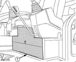
Cover
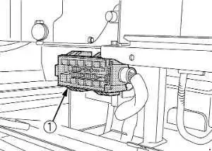

| No. | A | Description |
|---|---|---|
| 1 | 20 | Cab Light |
| 2 | 15 | Work Light |
| 3 | 5 | Meter (+B) |
| 4 | 10 | Horn |
| 5 | 5 | Room Light |
| 6 | 10 | Alternator |
| 7 | 5 | Cab Relay |
| 8 | 5 | Meter (AC) |
| 9 | 15 | ECU (AC) |
| 10 | 5 | Fuel Pump |
| 11 | 5 | Lever Lock |
| 12 | 5 | Starter |
| 13 | 15 | AI Motor |
| 14 | 10 | Horn SW |
| 15 | 5 | ECU (+B) |
| 16 | 15 | Beacon |
| 17 | 5 | A/C Controller (+B) |
| 18 | 30 | Engine Stop |
| 19 | 30 | Blower Motor |
| 20 | 15 | Electrical Outlet |
| 21 | 15 | Radio (AC) |
| 22 | 15 | Wiper / Washer |
| 23 | 10 | Compressor, A/C Controller (AC) |
Slow Blow Fuse
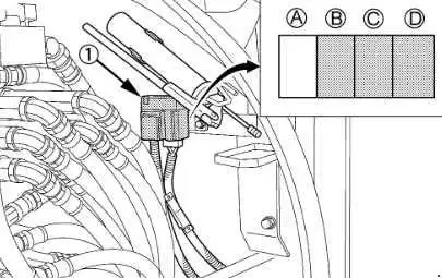
Slow blow fuse is provided to protect the electrical circuits. If the fusible link is blown, check the electrical circuits for trouble and then replace with a new compatible slow blow fuse.
| No. | A | Description |
|---|---|---|
| A | - | Not Used |
| B | 80 | Alternator |
| C | 50 | Main Power |
| D | 50 | Engine Stop Cab Relay (Blower Motor) |