1997–2006 Land Rover Freelander
Location and description of fuses Land Rover Freelander (L314) with petrol engine 1.8L, 2.5L V6 (KV6) or diesel engine 2.0L TD (1997, 1998, 1999, 2000, 2001, 2002, 2003, 2004, 2005, 2006)
| To prevent a possible fire or damage to the electrical system, only fit replacement fuses of the same rating and type. Do not replace a blown fuse with a fuse of a higher amperage rating. Always rectify the cause of the failure before replacing a fuse. Seek qualified assistance if necessary. |
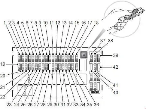
MAIN FUSE BOX (2004-2006)
LHD
RHD
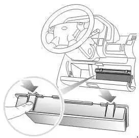
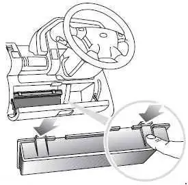
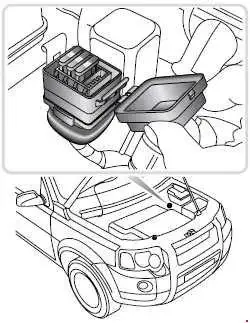
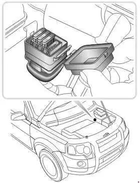
The main fusebox is located behind the driver's storage area. To access the fuses, open the storage area, depress the two catches arrowed in the illustration and remove the fuse box cover.
NOTE: A label in the fuse box cover shows the electrical circuits protected, the fuse values and their locations.
| No. | A | Description |
|---|---|---|
| 1 | 20 | Front screen wash/wipe |
| 2 | 15 | Stop lamps, reversing lamps |
| 3 | 15 | Heated mirrors/Rear screen wash |
| 4 | 25 | Heater blower |
| 5 | 10 | Starter motor |
| 6 | 10 | Cruise control/HDC/Automatic Gearbox start inhibit |
| 7 | 10 | Side lamps - LH |
| 8 | 25 | Driver’s front window lift |
| 9 | 15 | Cigar lighter |
| 10 | 20 | Electric accessories socket |
| 11 | 20 | Heated seats |
| 12 | 15 | Audio system - Vehicle battery power feed |
| 13 | 5 | Engine immobilisation |
| 14 | 15 | Headlamp main beam - RH |
| 15 | 10 | Door mirrors |
| 16 | 10 | Interior lights/Clock |
| 17 | 10 | Side lamps - RH |
| 18 | 15 | Instruments/Indicators |
| 19 | 10 | Headlamp dipped beam - RH |
| 20 | 10 | Headlamp dipped beam - LH |
| 21 | 15 | Sunroof |
| 22 | 10 | Engine management |
| 23 | 10 | Airbag |
| 24 | 5 | Parking aid |
| 25 | 5 | Anti-lock brakes |
| 26 | 20 | Heated rear window |
| 27 | 10 | Audio system |
| 28 | - | Not used |
| 29 | 5 | Electric windows |
| 30 | 15 | Front fog lamps |
| 31 | 20 | Taildoor glass lift/drop |
| 32 | 25 | Rear window lift - LH |
| 33 | 25 | Rear window lift - RH |
| 34 | 15 | Headlamp main beam - LH |
| 35 | 25 | Passenger front window lift |
| 36 | 10 | Rear fog lamps |
| 37 | 20 | Central door locking |
| 38 | 10 | Rear wiper |
| 39 | 10 | Front fog lamp switch |
| 40 | - | Not used |
| 41 | 10 | Alternator |
| 42 | - | Not used |
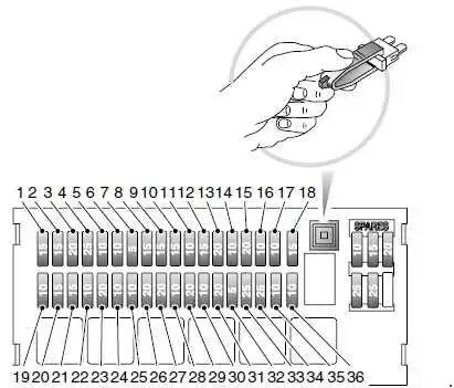
MAIN FUSE BOX (1997-2003)
| No. | A | Description |
|---|---|---|
| 1 | 15 | Rear windshield washers, heated mirrors |
| 2 | 15 | Stop lights, reversing lights |
| 3 | 20 | 2003: Windshield wash/wipe |
| 15 | →2002: Windshield wash/wipe | |
| 4 | 25 | Heater blower |
| 5 | 10 | Starter motor |
| 6 | 10 | Engine management |
| 7 | 5 | 2003: Anti-lock brakes |
| 10 | →2002: Anti-lock brakes | |
| 8 | 15 | Direction indicators |
| 9 | 15 | Audio system |
| 10 | 15 | Cigar lighter |
| 11 | 10 | Audio system |
| 12 | 15 | Sunroof |
| 13 | 20 | 2003: Electric accessories socket |
| 25 | →2002: Electric accessories socket | |
| 14 | 10 | Interior lights, clock, electric mirrors, diagnostic socket |
| 15 | 20 | Central door locking |
| 16 | 10 | Sidelights - RH |
| 17 | 10 | Electric mirrors |
| 18 | 15 | Headlight main beam - RH |
| 19 | 10 | Alternator |
| 20 | 15 | Headlight main beam - LH |
| 21 | 15 | Front fog lights |
| 22 | 10 | Rear fog guard lights |
| 23 | 20 | Rear windshield demister |
| 24 | 10 | Headlight dipped beam - LH |
| 25 | 10 | Headlight dipped beam - RH |
| 26 | 20 | Window - rear LH |
| 27 | 20 | Window - rear RH |
| 28 | 10 | Sidelights - LH |
| 29 | 20 | Heated seats |
| 30 | 10 | Rear windshield wiper |
| 31 | 20 | Taildoor glass lift/drop |
| 32 | 5 | 2003: Engine immobilisation |
| 20 | →2002: Engine immobilisation Anti-lock brakes | |
| 33 | 25 | 2003: Window - front LH |
| 20 | →2002: Window - front LH | |
| 34 | 25 | 2003: Window - front RH |
| 20 | →2002: Window - front RH | |
| 35 | 10 | Cruise control, engine immobilisation |
| 36 | 10 | Airbag SRS |
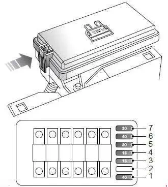
ENGINE COMPARTMENT FUSE BOX (2003-2006)
The engine compartment fuse box is located on the left side of the engine compartment.
| No. | A | Description |
|---|---|---|
| 1 | 15 | Engine management |
| 2 | 20 | Engine management |
| 3 | 15 | Engine management |
| 4 | 15 | Air conditioning, cooling fan, automatic gearbox |
| 5 | 20 | Engine management, transmission cooling fan, fuel burning heater |
| 6 | 15 | Horn |
| 7 | 15 | Hazard warning lamps |
| 8 | 30 | Heater blower speed 4 |
| 9 | 10 | Air conditioning |
| 10 | 20 | Fuel system |
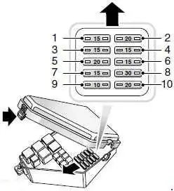
ENGINE COMPARTMENT FUSE BOX (1997-2002)
| No. | A | Description |
|---|---|---|
| 1 | 40 | Cooling fan |
| 2 | - | - |
| 3 | 15 | Horn |
| 4 | 15 | Hazard warning lights |
| 5 | 20 | Fuel pump and fuel injectors |
| 6 | 40 | Condenser fan |
| 7 | 30 | Starter solenoid |
| 120 | ALTERNATOR | |
| 60 | IGNITION 1 | |
| 60 | PASSENGER FUSEBOX | |
| 60 | IGNITION 2 | |
| 60 | LIGHTING | |
| 30 | ABS PUMP |
SUPPLEMENTARY FUSE BOX
An additional, supplementary fuse box is fitted to some vehicles, containing fuses for the heated front screen.
| No. | A | Description |
|---|---|---|
| 1 | 30 | LH heated front screen |
| 2 | 30 | RH heated front screen |
| 3 | 7.5 | Switch illumination |
| 4 | - | - |
Fuse specification for vehicles with a PTC system heater
| No. | A | Description |
|---|---|---|
| 1 | 30 | PTC heater |
| 2 | 30 | PTC heater |
| 3 | 30 | PTC heater |
| 4 | - | - |