2003-2008 Toyota Corolla (USA)

Location and description of fuses and relays Toyota Corolla CE, LE & S (E120; only USA) with gasoline engine 1.8L VVT-i 1ZZ-FE or 1.8L VVTL-i 2ZZ-GE (2003, 2004, 2005, 2006, 2007, 2008)
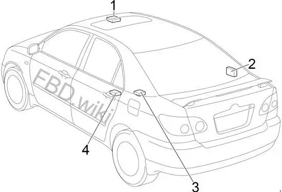
Passenger Compartment
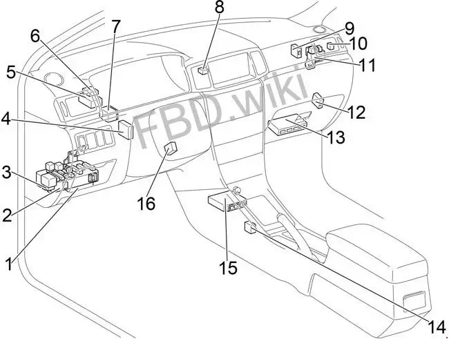
- Integration Relay
- Fuse Box
- Turn Signal Flasher Relay
- Daytime Running Light Relay
- Cruise Control ECU
- Transponder Key Computer
- Junction Block
- Antenna Amplifier
- Glass Breakage Sensor ECU
- Starter Cut Relay
- Relay Box
- TVIP ECU
- Engine Control Module
- Shift Lock Control ECU
- Airbag Sensor Assembly
- Transponder Key Amplifier
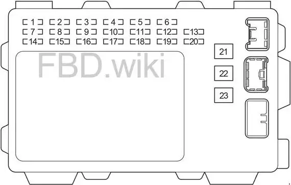
Passenger Compartment Fuse Box
| No. | Name | A | Description |
|---|---|---|---|
| 1 | TAIL | 15 | Tail lights, license plate lights, instrument panel lights, instrument cluster lights |
| 2 | OBD | 7.5 | On−board diagnosis system |
| 3 | - | - | - |
| 4 | P/W | 30 | - |
| 5 | WIPER | 25 | Windshield wipers |
| 6 | AM2 | 15 | Charging system, multiport fuel injection system/sequential multiport fuel injection system, starting system, SRS airbag system |
| 7 | STOP | 15 | Stop lights, high mounted stoplight, anti−lock brake system, shift lock control system, multiport fuel injection system/sequential multiport fuel injection system, cruise control system |
| 8 | DOOR | 25 | Power door lock system |
| 9 | AM1 | 25 | “CIG” fuse |
| 10 | - | - | - |
| 11 | ECU-IG | 10 | Electric cooling fan, anti−lock brake system, vehicle stability control system, traction control system, brake assist system, shift lock control system, cruise control system |
| 12 | RR WIPER | 15 | Rear wiper |
| 13 | A/C | 10 | Air conditioning system |
| 14 | INV | 15 | - |
| 15 | P/POINT | 15 | Power outlet (in the rear console box) |
| 16 | ECU-B | 10 | Daytime running light system |
| 17 | CIG | 15 | Power outlet (on the instrument panel) or cigarette lighter, car audio system, clock, power rear view mirror control, shift lock control system |
| 18 | GAUGE | 10 | Gauges and meters, air conditioning system, daytime running light system, charging system, auto anti−glare inside rear view mirror, power windows, cruise control system, rear window defogger, back−up lights, front passenger’s seat belt reminder light |
| 19 | WASHER | 15 | Windshield washer |
| 20 | M-HTR/DEF I-UP | 10 | Engine control system |
| 21 | HEATER | 40 | Air conditioning system |
| 22 | DEFOG | 40 | Rear window defogger, “M−HTR/DEF I−UP” fuse |
| 23 | POWER | 30 | Power windows, electric moon roof |
| No. | Description |
|---|---|
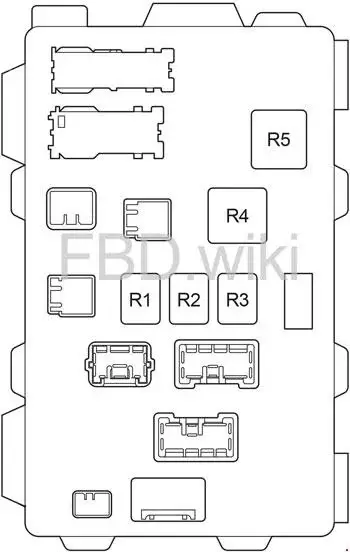
| R1 | Circuit opening (Fuel pump (C/OPN)) |
| R2 | Power window (P/W) |
| R3 | Ignition (IG1) |
| R4 | Rear windshield defogger (DEF) |
| R5 | Starter (ST) |
Passenger Compartment Relay Box
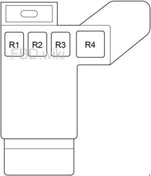
| No. | Description |
|---|---|
| R1 | - |
| R2 | Tail lights (TAIL) |
| R3 | Power point (P-POINT) |
| R4 | Heater (HTR) |
- Moon Roof Control Relay and Switch
- Door Control Receiver
- Stereo Component Amplifier
- Occupant Classification ECU
Engine Compartment
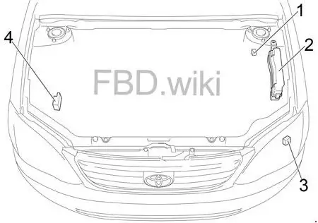
- Relay Box
- Fuse Box
- Air Pump Relay
- Skid Control ECU with Actuator
Engine Compartment Fuse Box
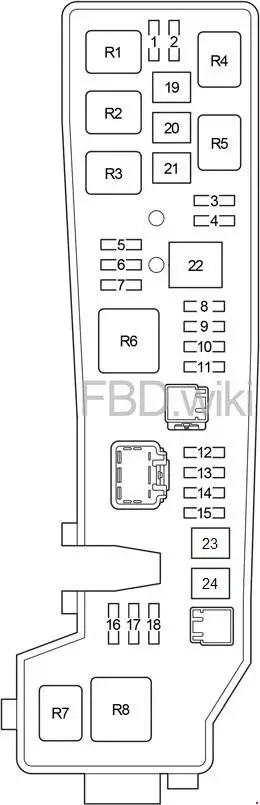
| No. | Name | A | Description | |
|---|---|---|---|---|
| 1 | - | - | - | |
| 2 | FOG | 15 | Front fog lights | |
| 3 | HEAD LH UPR | 10 | Left−hand headlight (high beam) | |
| 4 | HEAD RH UPR | 10 | Right−hand headlight (high beam), high beam indicator light | |
| 5 | - | - | - | |
| 6 | - | - | - | |
| 7 | - | - | - | |
| 8 | ETCS | 10 | 1ZZ-FE: Electronic throttle control system | |
| 9 | AMP | 30 | Audio system | |
| 10 | MAIN | 30 | Starting system, “AM2” fuse | |
| 11 | DOME | 15 | Audio system, clock, personal lights, interior light, trunk light, open door warning light, wireless remote control system | |
| 12 | HORN | 10 | Horn | |
| 13 | HAZARD | 10 | Emergency flashers, turn signal lights | |
| 14 | EFI | 20 | 1ZZ-FE: Multiport fuel injection system/sequential multiport fuel injection system, emission control system, “EFI2” fuse | |
| 10 | 2ZZ-GE: Multiport fuel injection system/sequential multiport fuel injection system, emission control system | |||
| 15 | ALT-S | 5 | Charging system | |
| 16 | EFI2 | 15 | 1ZZ-FE: Multiport fuel injection system/ sequential multiport fuel injection system, emission control system | |
| 17 | HEAD RH LWR | 10 | Right−hand headlight (low beam) | |
| 18 | HEAD LH LWR | 19 | Left−hand headlight (low beam) | |
| 19 | ABS NO.1 | 30 | Anti−lock brake system, vehicle stability control system, traction control system, brake assist system | |
| 20 | RDI FAN | 30 | Electric cooling fan | |
| 21 | ABS NO.2 | 50 | with VSC: Anti−lock brake system, vehicle stability control system, traction control system, brake assist system | |
| 40 | without VSC: Anti−lock brake system | |||
| 22 | ALT | 100 | Charging system, “ABS NO.1”, “ABS NO.2”, “RDI FAN”, “FOG”, “HTR”, “AM1”, “POWER”, “DOOR”, “ECU−B”, “TAIL”, “STOP”, “P/POINT”, “INV” and “OBD” fuses | |
| 23 | HEAD MAIN | 40 | “HEAD LH UPR”, “HEAD RH UPR”, “HEAD LH LWR” and “HEAD RH LWR” fuses | |
| 24 | AIR PUMP | 50 | 2ZZ-GE: Emission control system | |
| Relay | ||||
| R1 | Electric cooling fan (FAN NO.1) | |||
| R2 | Electric cooling fan (FAN NO.2) | |||
| R3 | Horn | |||
| R4 | Front fog light (FOG) | |||
| R5 | Engine control unit (EFI) | |||
| R6 | Dimmer (DIMMER) | |||
| R7 | Air conditioner compressor clutch (M/G CLT) | |||
| R8 | Headlight (HEAD) | |||
Engine Compartment Relay Box
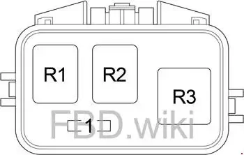
| No. | Name | A | Description |
|---|---|---|---|
| 1 | - | - | - |
| Relay | |||
| R1 | - | ||
| R2 | Anti−lock brake system (ABS MTR CUT) | ||
| R3 | Anti−lock brake system (ABS MTR) | ||