2009-2015 Ferrari 458
Location and description of fuses and relay Ferrari 458 Italia, 458 Spider and 458 Speciale with engine 4.5L V8 Ferrari F136 (2009, 2010, 2011, 2012, 2013, 2014, 2015)
Location
458 Spider
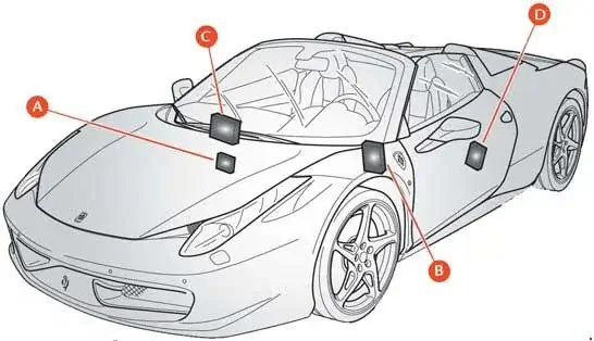
458 Speciale
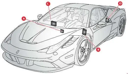
A - Fuses and relays in battery compartment
B - Body Computer fuses and relays
C - Fuses and relays in passenger compartment on passenger side
D - Fuses and relays on driver-side rear side panel
Body Computer fuses and relays
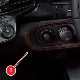
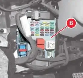
| No. | A | Description |
|---|---|---|
| F12 | 15 | Bight high beam |
| F13 | 15 | Left high beam |
| F31 | 7.5 | ENT/A for dashboard ECU and Body Computer Node relay coils |
| F32 | 10 | Dome lights, foot well and step lights. Side Marker relay coil |
| F33 | 30 | Speciale: Left hand Brembo EPB system motor |
| F34 | 30 | Spider: Suspension Control Node Speciale: Right hand Brembo EPB system motor |
| F35 | 7.5 | Stop light control, clutch control, air conditioning node |
| F36 | 10 | Volumetric and-theft system, parking sensors, fuel filler flap relay coil |
| F37 | 10 | Stop light control, Instrument Panel Node, Suspension Control Node |
| F38 | 15 | Luggage compartment lock actuator |
| F39 | 15 | Dashboard ECU devices (NBC interconnection) |
| F40 | 30 | Heated rear window |
| F42 | 7.5 | Alternator |
| 15 | Speciale: USB charging socket | |
| F43 | 30 | Windscreen washer/wiper relay power supply |
| F44 | 20 | Passenger seat heating, cigarette lighter |
| F47 | 30 | Driver-side door, driver-side power window |
| F48 | 30 | Passenger-side door, passenger-side power window |
| F49 | 7.5 | Rain and twilight sensor, parking sensors, parking brake control, column adjustment control, hazard warning lights, Steering Wheel Node, Differential Control Node, radio, CAN box interface |
| F50 | 7.5 | Airbag Node, weight sensor |
| F51 | 7.5 | Semi-automatic Gearbox Node |
| F52 | 15 | Power socket, driver seat heating |
| F53 | 10 | Instrument Panel Node power supply |
| Relay | ||
| T01 | 20 | Low beam relay |
| T11 | 30 | Heated rear window relay |
| T12 | 30 | Service relay 1 (dependent on INT/A ignition switch) |
| T13 | 50 | Jumper (service power supply 2) |
Fuses and relays in passenger compartment on passenger side
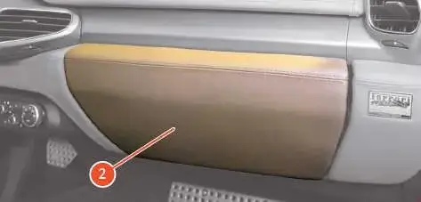
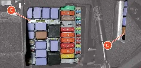
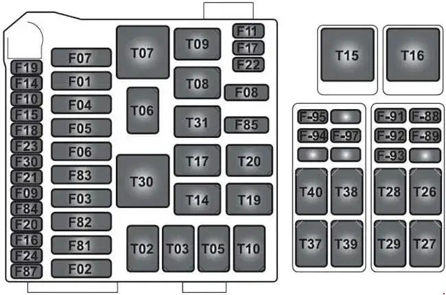
| No. | A | Description |
|---|---|---|
| F01 | 60 | Spider: +30 Radiator fan relay 2 |
| 40 | Speciale: Right hand radiator fan relay | |
| F02 | 30 | Spider: +30 ABS (valves) Speciale: F97, F98 protection fuses for ABS |
| F03 | 30 | Spider: +30 Hard top Node (pump) |
| F04 | 50 | +30 ABS (pump) |
| F05 | 40 | +30 Air conditioning Node |
| F06 | 50 | Spider: +30 Radiator fan relay 1 |
| 40 | Speciale: Left hand radiator fan relay | |
| F07 | 20 | +30 Horn relay |
| F08 | 7.5 | Air conditioning and heating system compressor |
| F09 | 7.5 | +30 Supplementary stop light relay (third stop light) |
| F10 | 15 | Spider: +30 Fuel pump relay 1 Speciale: Tyre pressure monitoring system + DRL ECU |
| F11 | 25 | Left bank oxygen sensor |
| F14 | 15 | Spider: +30 High beam relay |
| 10 | Speciale: +30 High beam relay | |
| F15 | 7.5 | Spider: +30 Power supply for EPB-activated stop light control relay, right headlight LED module power supply relay |
| 10 | Speciale: +30 Power supply for EPB-activated stop light control relay, right headlight LED module power supply relay | |
| F16 | 25 | +30 Right bank engine control power supply |
| F17 | 25 | +30 Left bank engine control power supply |
| F18 | 10 | +30 Left cylinder bank injection system power supply, LH cylinder bank injection main relay |
| F19 | 10 | +30 Right cylinder bank injection system power supply |
| F20 | 30 | +30 Right cylinder bank injection system main relay |
| F21 | 15 | Spider: +30 Fuel pump relay 2 |
| 30 | Speciale: +30 Ignition switch protection | |
| F22 | 15 | Left bank (ignition coil) |
| F23 | 10 | Spider: +30 ABS (electronic) |
| 30 | Speciale: Suspension Control Node | |
| F24 | 15 | Right bank (ignition coil) |
| F30 | 30 | +30 HI-FI amplifier relay |
| F81 | 40 | Spider: +30 Supplementary ECU power siupply |
| 50 | Speciale: Fuel pump ECU | |
| F82 | 70 | +30 Dashboard ECU and ECU oi rear side panel power supplyii driver-side |
| F83 | 50 | +30 Air pump relay |
| F84 | 15 | Spider: +30 Fuel pump relay 1 |
| 30 | Speciale: Protection for fuses F94 F95 F96 | |
| F85 | 25 | Headlight washer |
| F87 | 25 | Right bank oxygen sensors |
| F88 | 10 | +15 Left cylinder bank injection system |
| F89 | 10 | +15 Right cylinder bank injection system |
| F91 | 15 | Spider: +30 Tyre pressure node, LH headlight LED module relay |
| 10 | Speciale: Left hand cylinder bank sensors | |
| F92 | 7.5 | Spider: +30 Alternator sensing |
| 10 | Speciale: Right hand cylinder bank sensors | |
| F93 | 30 | Spider: +30 Ignition switch |
| 7.5 | Speciale: Ionising engine ECU | |
| F94 | 15 | +30 Radio/CAN box/ICP/dock spring/Japan navigation system stabiliser |
| F95 | 10 | +30 Current stabiliser |
| F96 | 7.5 | Speciale: +15 ignition switch, stabilised for buttons |
| F97 | 30 | Spider: +30 Stabiliser for Becker amplifier Speciale: ABS hydraulics |
| F98 | 10 | Speciale: ABS electronics |
| Relay | ||
| T02 | 30 | High beam relay |
| T03 | 30 | Spider: Fuel pump second speed relay |
| T05 | 30 | Spider: Fuel pump relay 2 |
| T06 | 30 | Spider: Glove compartment relay |
| T07 | 50 | Horn relay |
| T08 | 30 | Air conditioning and heating system compressor relay |
| T09 | 30 | Left cylinder bank injection system main relay |
| T10 | 30 | Right cylinder bank injection system main |
| T14 | 30 | Spider: Fuel pump relay 1 |
| T17 | 10 20 | INT/A relay (devices excluded at ignition) |
| T19 | 30 | EPB-activated stop light control relay |
| T20 | 30 | Spider: Starting relay |
| T26 | 10 20 | Windscreen wiper first speed relay |
| T27 | 10 20 | Windscreen wiper second speed relay |
| T28 | 30 | Windscreen washer pump relay |
| T29 | 30 | Supplementary stop light relay (third stop light) |
| T30 | 50 | Air pump relay |
| T31 | 30 | Headlight washer pump relay |
| T37 | 30 | Spider: Radiator fan relay 2 Speciale: +15 stabilised power for button backlighting |
| T38 | 30 | Left headlight LED module power supply |
| T39 | 30 | Right headlight LED module power supply |
| T40 | 30 | Spider: Radiator fan relay 1 Speciale: Start enable relay |
Fuses and relays on driver-side rear side panel
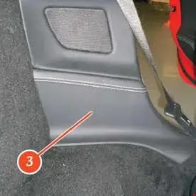
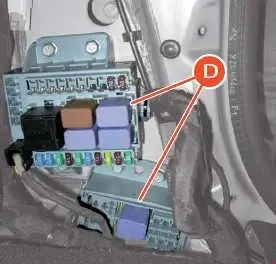
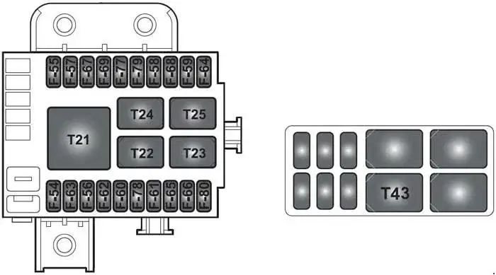
| No. | A | Description |
|---|---|---|
| F54 | 15 | +30 Gearbox cooling fan |
| F56 | 30 | Spider: +30 Driving Position Node |
| F57 | 7.5 | Side Markers 1 (LH front and RH rear) |
| F59 | 7.5 | Reverse light power supply |
| F60 | 30 | Spider: +30 Passenger Position Node Speciale: Active aerodynamics |
| F61 | 7.5 | +30 Driver Position Node (electronic), front lift |
| F62 | 7.5 | Spider: +30 Passenger Position Node (electronic) |
| F63 | 15 | Spider: +30 Semi-automatic gearbox main relay |
| 20 | Speciale: +30 Semi-automatic gearbox main relay | |
| F64 | 7.5 | Fuel filler flap actuator power supply |
| F65 | 20 | +30 Door lock actuator |
| F66 | 7.5 | +30 Semi-automatic Gearbox Node |
| F67 | 7.5 | Side Markers 2 (RH front and LH rear) |
| F78 | 15 | +30 Battery charger |
| F80 | 30 | +30 Starting relay |
| Relay | ||
| T21 | 50 | Side Marker relay |
| T22 | 30 | Reverse light relay |
| T23 | 30 | Fuel filler flap relay |
| T24 | 30 | Gearbox cooling fan relay |
| T25 | 30 | Semi-automatic gearbox main relay |
| T43 | 30 | Spider: Start enable relay |
| R1 | - | Starter power relay |
| R2 | - | Starter power relay |
Fuses and relays in battery compartment
458 Spider
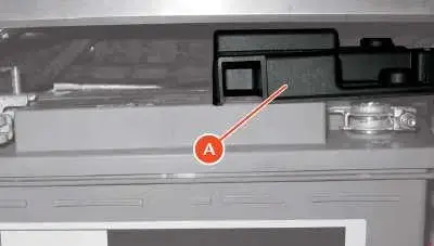
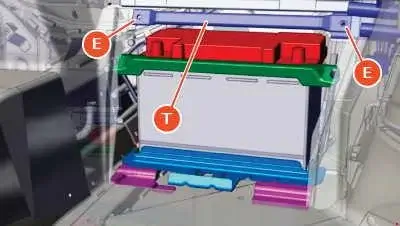
To access these fuses:
• remove the passenger footrest;
• using the hex-head wrench in the tool bag, remove the crossbar T by unscrewing the two screws E;
• remove the cover of box A located above the positive terminal on the right side of the battery.
458 Speciale
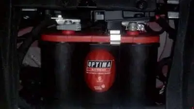
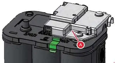
To access these fuses, remove the cover of the box A situated above the positive terminal on the right hand side of the battery.
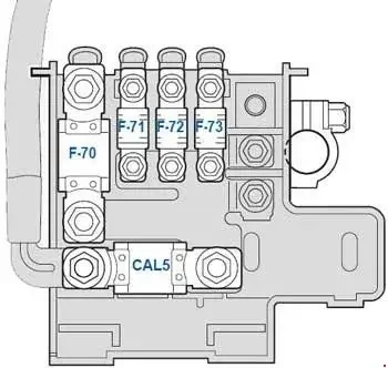
| No. | A | Description |
|---|---|---|
| CAL5 | CAL5 | Power supply (starter motor and alternator) |
| F70 | 150 | Engine relay and fuse ECU power supply (SCM) |
| F71 | 40 | Front lift pump |
| F72 | 40 | Spider: Parking brake power |
| F73 | 70 | Dashboard ECU power |