2017-2022 Mini Countryman (F60)

Fuse Box Layout Mini Countryman Cooper, Cooper S, John Cooper Works, One, One D & Cooper D (F60; 2017, 2018, 2019, 2020, 2021, 2022)
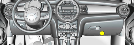
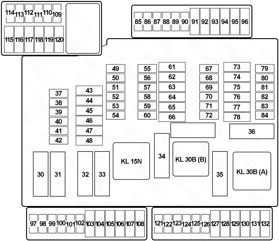
Passenger Compartment Fuse Box No.1
| No. | A | Protected Component |
|---|---|---|
| 30 | - | - |
| 31 | 50 | Heated Windscreen Relay |
| 32 | 40 | Body Domain Controller |
| 33 | - | - |
| 34 | 40 | Blower Output Stage |
| 35 | 50 | Body Domain Controller |
| 37 | 5 | Parking Brake Button |
| 38 | 5 | Siren with Tilt Alarm Sensor |
| 39 | 5 | Roof Function Centre (Airbag Indicator Lamp) |
| 40 | 5 | Dynamic Stability Control (DSC) |
| 41 | 5 | Instrument Cluster Control Unit |
| 42 | 5 | Remote Control Receiver (Comfort Access, Central Locking System, Tyre Pressure Control) |
| 43 | 30 | Roof Function Centre |
| 44 | 20 | Right Headlight |
| 45 | 30 | without Electromechanical Parking Brake: Dynamic Stability Control (DSC) |
| 40 | with Electromechanical Parking Brake: Dynamic Stability Control (DSC) | |
| 46 | 5 | except Cooper SE: Natural Vacuum Leak Detection |
| 10 | Cooper SE: Pressurised Fuel Tank Control Module | |
| 47 | 20 | Left Headlight |
| 48 | 30 | Selective Catalytic Reduction (SCR) Control Unit |
| 49 | 5 | Electrical Exhaust Flap, Control Electronics for Electric Auxiliary Heater No.2 |
| 50 | 5 | Radiator Shutter Drive Unit, Environmental Air Catalyst Sensor (except Cooper SE) |
| 51 | 5 | Base Plate Fan |
| 52 | 5 | Electrochromic Interior Rear View Mirror |
| 53 | 5 | Automatic Recirculated Air Control (AUC) Sensor |
| 54 | 5 | Electromechanical Power Steering |
| 55 | 4 | Reversing Camera, Parking Assistant |
| 56 | 5 | except Cooper SE: Longitudinal Torque Distribution |
| 5 | Cooper SE: Longitudinal Torque Distribution, Vehicle Sound Generator 1 & 2 | |
| 57 | - | - |
| 58 | 10 | Steering Column Switch Cluster |
| 59 | 5 | Camera-Based Driver Assistance System |
| 60 | 5 | Optional Extra System |
| 61 | 20 | Headunit (Radio or Navigation System) |
| 62 | 5 | Interior Light, Rain Light Solar Condensation Sensor, Vanity Mirror Light, Third Row of Seats Interior Light |
| 63 | 20 | Trailer Socket |
| 64 | - | - |
| 65 | 20 | Front Cigarette Lighter (12 V Power Socket) |
| 66 | 20 | Electric Fuel Pump Control Electronics |
| 67 | 5 | Exterior Mirror (Front Passenger) |
| 68 | 5 | Touchbox, Controller (CON), USB Hub, USB Charging Socket No.3 |
| 69 | 5 | Exterior Mirror (Switch Block - Driver's Door) |
| 70 | 5 | Luggage Compartment Light, Glove Compartment Light, Rear Lid Button on Inside of Rear Lid |
| 71 | 7.5 | Instrument Cluster Control Unit |
| 72 | 5 | Fan 400W→: Electric Fan Cut-Out Relay |
| 5 | Fan →400W: Integrated Supply Module | |
| 73 | 10 | Driver's Seat Backrest width Adjustment Valve Block, Driver Lumbar Support Valve Block, Switch for Backrest width Adjustment Driver's Seat |
| 74 | 7.5 | Petrol: Turbocharger Coolant Pump (TU) |
| 75 | 10 | Front Passenger Seat Backrest width Adjustment Valve Block, Front Passenger Lumbar Support Valve Block, Switch for Backrest width Adjustment Front Passenger |
| 76 | 10 | Diesel: Diesel Particulate Sensor |
| 77 | 10 | Nitrogen Oxide Sensor after Selective Catalytic Reduction (SCR) Catalytic Converter |
| 78 | 15 | Selective Catalytic Reduction (SCR) Control Unit |
| 79 | 5 | Base Plate, Wireless Charging Oddments Tray, Wireless Charging Oddments Tray Aerial Amplifier |
| 80 | 5 | Central Instrument, Central Information Display |
| 81 | 15 | Electronic Transmission Control |
| 82 | 5 | Selector Level |
| 83 | 7.5 | Petrol: Digital Motor Electronics |
| 84 | 5 | Clutch Module (Manual Transmission), Twin-Clutch Gearbox Control Unit, Twin-Clutch Gearbox Relay |
| 85 | 5 | Electrochromic Interior Rear View Mirror |
| 86 | - | - |
| 87 | - | - |
| 88 | - | - |
| 89 | - | - |
| 90 | - | - |
| 91 | 15 | Active Sound Design |
| 92 | 10 | Optional Extra System |
| 93 | - | - |
| 94 | - | - |
| 95 | 30 | Front Passenger Side Seat Adjustment Switch Block |
| 96 | 10 | Boot Lid/Tailgate Lock |
| 97 | - | - |
| 98 | 5 | Preparation of Tall Function |
| 99 | - | - |
| 100 | 5 | Cooper SE: High-Voltage Battery Unit |
| 101 | 5 | ID Reader, Car Sharing Module (CSM) |
| 102 | - | - |
| 103 | 20 | Right Headlight |
| 104 | 20 | Left Headlight |
| 105 | - | - |
| 106 | - | - |
| 107 | 40 | →06.17: Automatic Luggage Compartment Lid Actuation |
| 40 | 07.17→: Tailgate Function Module | |
| 108 | - | - |
| 109 | 5 | Bi-Stable Relay |
| 110 | 5 | Bi-Stable Relay |
| 111 | 5 | Bi-Stable Relay |
| 112 | - | - |
| 113 | - | - |
| 114 | - | - |
| 115 | 5 | Cooper SE: Convenience Charging Electronics |
| 116 | - | - |
| 117 | - | - |
| 118 | - | - |
| 119 | 20 | Trailer Module, Trailer Socket |
| 120 | 20 | Trailer Module, Trailer Socket |
| 121 | 7.5 | USB Charging Socket No.4 (Rear) |
| 122 | 5 | Safety Battery Terminal Gas Generator |
| 123 | 5 | Electrical A/C Compressor, Electric Auxiliary Heater |
| 124 | 10 | Cooper SE: Electric-Machine Electronics |
| 125 | - | - |
| 126 | - | - |
| 127 | 30 | Driver's Seat Heating Electronics (Basic Version), Driver's Seat Module (High Version) |
| 128 | 30 | Front Passenger Seat Heating Electronics |
| 129 | 30 | HiFi Amplifier |
| 130 | 10 | Cooper SE: Coolant Pump 2 in Low-Temperature Coolant Circuit |
| 131 | 30 | except Cooper SE: Longitudinal Torque Distribution |
| 30 | Cooper SE: Transmission Oil Pump, Longitudinal Torque Distribution | |
| 132 | 20 | 12 V Power Socket No.1, 12 V Power Socket No.2 (→06.18), 12 V Power Socket No.4 (Luggage) |
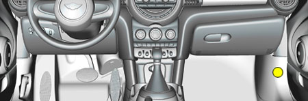
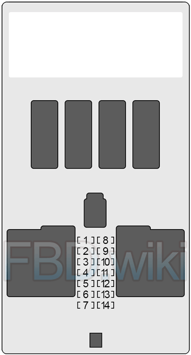
Passenger Compartment Fuse Box No.2
| No. | A | Protected Component |
|---|---|---|
| 1 | 30 | Passenger Power Window |
| 2 | 30 | Rear Driver's Side Power Window |
| 3 | 20 | Front Passenger Door Lock |
| 4 | 30 | Driver Power Window |
| 5 | 30 | Rear Window Defogger |
| 6 | 30 | Rear Passenger Side Power Window |
| 7 | 20 | Driver's Door Lock |
| 8 | - | - |
| 9 | 5 | Light Operating Unit, Steering Column Switch Cluster, Driver Assistance System Operating Facility with Hazard Warning Switch |
| 10 | 7.5 | Diagnosis Socket |
| 11 | 7.5 | Heating/Air Conditioning System, Tailgate Function Module |
| 12 | 5 | Evaluation Electronics for Contact-Free Tailgate Opening, Telematic Communication Box, Electronic Outer Door Handle Module (Driver/Passenger) |
| 13 | 15 | Horn |
| 14 | 15 | Rear Wiper & Washer |
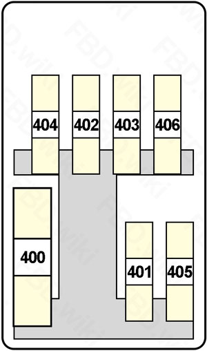
Fusible Link Block
| No. | A | Protected Component |
|---|---|---|
| 400 | 250 | Front Power Distribution Box |
| 401 | 60 | Fan →400W: Electric Fan Cut-Out Relay |
| 80 | Fan 600W: Electric Fan Cut-Out Relay | |
| 125 | Fan 850W: Electric Fan Cut-Out Relay | |
| 402 | 125 | Electromechanical Power Steering |
| 403 | 50 | →06.18: Dynamic Stability Control (DSC) |
| 60 | 07.18→: Dynamic Stability Control (DSC) | |
| 404 | 125 | Body Domain Controller |
| 405 | 100 | Front Electric Auxiliary Heater |
| 406 | 40 | Diesel: Fuel Filter Heating |
| 40 | Steptronic with Double Clutch: Twin-Clutch Gearbox Relay | |
| 60 | Control Electronics for Electric Auxiliary Heater in Engine Compartment |
Integrated Supply Module (Petrol)
- 1.5L - B38 (One, Cooper), 2.0L - B48 (Cooper S, JCW) and Hybrid 1.5L - B38 (Cooper SE) - except TU / TU
!!! The integrated supply module contains fuses and relays. If one of the fuses or one of the relays is faulty, the complete integrated supply module must be renewed !!!
| No. | A | Protected Component |
|---|---|---|
| 01 | 20 | except TU, Cooper SE: Digital Motor Electronics (DME) |
| 7.5 | TU: Heat Management Module, Oil Pressure Control Valve, Oil-Level Sensor | |
| 02 | 15 | except TU, Cooper SE: Digital Motor Electronics (DME) |
| 03 | 10 | except TU, Cooper SE: Digital Motor Electronics (DME) |
| 04 | 15 | except TU, Cooper SE: Digital Motor Electronics (DME) |
| 15 | TU: Engine Ventilation Heating | |
| 05 | 20 | except TU, Cooper SE: Digital Motor Electronics (DME) |
| 20 | TU: Oxygen Sensor after Catalytic Converter, Oxygen Sensor before Catalytic Converter | |
| 06 | 40 | except TU, Cooper SE: Digital Motor Electronics (DME) |
| 07 | 50 | except TU, Cooper SE: Electric Fan |
| 08 | 15 | TU: Digital Motor Electronics (DME) |
| 09 | 40 | TU: Starter |
| 010 | 30 | TU: Digital Motor Electronics (DME) |
| 011 | 20 | TU: Digital Motor Electronics (DME) |
| 014 | 40 | TU: Digital Motor Electronics (DME) |
| 018 | 10 | TU: Digital Motor Electronics (DME), Intake VANOS Solenoid Actuator, Exhaust VANOS Solenoid Actuator, Tank Vent Valve |
Power Distribution Box (Diesel)
!!! The integrated supply module contains fuses and relays. If one of the fuses or one of the relays is faulty, the complete integrated supply module must be renewed !!!
| No. | A | Protected Component |
|---|---|---|
| 01 | 20 | Preheating Control Unit, Rail Pressure Regulating Valve, Fuel Quantity Control Valve, Oil Pressure Control Valve, Coolant Pump Changeover Valve, Pressure Converter - Turbine Control Flap (2.0L B47 TOP), Charging Pressure Controller - Low Pressure Stage (2.0L B47 TOP) |
| 02 | 20 | Oil Level Sensor, Oxygen Sensor after Catalytic Converter, EGR Cooler Bypass Flap Changeover Valve, Oxygen Sensor before Catalytic Converter, Changeover Valve - Compressor Bypass Plate (2.0L B47 TOP) |
| 03 | 20 | Digital Diesel Electronics (DDE) |
| 04 | 20 | Digital Diesel Electronics (DDE) |
| 05 | 20 | Digital Diesel Electronics (DDE) |
Integrated Supply Module (Diesel)
!!! The integrated supply module contains fuses and relays. If one of the fuses or one of the relays is faulty, the complete integrated supply module must be renewed !!!
| No. | A | Protected Component |
|---|---|---|
| 01 | 7.5 | Oil Pressure Control Valve, Oil-Level Sensor, Compressor Bypass Plate Changeover Valve (except 2.0L B47) |
| 02 | 7.5 | Coolant Pump Changeover Valve, Piston Cooling Solenoid Valve |
| 03 | 7.5 | Fuel Quantity Control Valve |
| 04 | 7.5 | except B47 TOP: Turbine Control Flap Pressure Converter |
| 7.5 | B47 TOP: Coolant Shutoff Valve for Low-Pressure Stage Turbocharger | |
| 05 | 15 | Digital Diesel Electronics (DDE) |
| 06 | 20 | EGR Cooler Bypass Flap Changeover Valve, Nitrogen Oxide Sensor before SCR Catalytic Converter |
| 07 | 15 | Oxygen Sensor before Catalytic Converter, Oxygen Sensor after Catalytic Converter |
| 08 | 5 | Digital Diesel Electronics (DDE), Rail Pressure Regulating Valve |
| 09 | 40 | Starter |
| 010 | 30 | Digital Diesel Electronics (DDE) |
| 011 | 40 | Fuel Filter Heating |
| 014 | 40 | Digital Diesel Electronics (DDE) |
| 015 | 40 | Digital Diesel Electronics (DDE) |